Energy Band Structure Of Pn Junction Diode

P N Junction Diode Junction Diode Biasing Forward Bias And

P N Junction Diode Junction Diode Biasing Forward Bias And

8 Draw The Energy Band Diagram Of An Unbiased P N Junction

8 Draw The Energy Band Diagram Of An Unbiased P N Junction

Energy Band Diagram Of Pn Junction A Zero Bias B Forward

Energy Band Diagram Of Pn Junction A Zero Bias B Forward


Energy Band Diagram Of Pn Junction A Zero Bias B Forward
Electrostatic Analysis Of A P N Diode
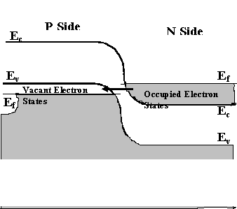
Electrostatic Analysis Of A P N Diode

Computer Simulation Of P N Junction Devices

Computer Simulation Of P N Junction Devices

Itm University Cse Section B Physics Experiment 9

Itm University Cse Section B Physics Experiment 9

Energy Band Diagram Of P N Junction Diode Lessons Tes Teach

Energy Band Diagram Of P N Junction Diode Lessons Tes Teach

Analogue Electronics Pn Junctions Wikibooks Open Books

Analogue Electronics Pn Junctions Wikibooks Open Books

Semiconductors Electrical Properties Of Materials Part 3

Semiconductors Electrical Properties Of Materials Part 3

Pn Junction Modern Lab Experiments Documentation

Pn Junction Modern Lab Experiments Documentation

Development Of Animated Simulation Of Semiconductor

Development Of Animated Simulation Of Semiconductor

5 5 The Energy Band Diagram For A Reverse Biased S

5 5 The Energy Band Diagram For A Reverse Biased S

Itm University Cse Section B Physics Experiment 9

Itm University Cse Section B Physics Experiment 9

4 Energy Band Diagram Of Simple P N Junction Under

4 Energy Band Diagram Of Simple P N Junction Under

Energy Band Gap In Pn Junction Diodes Trainer Kits

Energy Band Gap In Pn Junction Diodes Trainer Kits

Comments

Popular posts from this blog

Induction Coil Free Energy

Teslas free energy system is a self oscillating capacitive system. If you do this on a big scale and you can you create a radio black spot and quickly upset the owners of the transmitting station. Chapter 5 Energy Tapping Pulsed Systems What Is Faraday S Law Article Khan Academy A small amount of charge moves through the system per cycle that is the coulomb per seconds amps are low. Induction coil free energy . Designing the h bridge series resonant driver circuit. So far the information should have enlightened you regarding how to configure a simple induction cookware or an induction cooktop design however the most critical part of the design is how to resonate the coil capacitor network the tank circuit into the most optimal range so that the circuit works at the most efficient level. The theory is that electromagnetic fields around power lines create curr

In5408 Diode Radio Shack

Radio Shack Half Wave Rectifier Diode Pre 1950 Antique Electronics What Is A Diode Librar Wiring 101 Details About 10 Pcs 1n5408 Diode 3a 1000v Bridge Rectifier Diode High Quality Usa Seller 3 Phase Diode Rectifier Classifieds Project Articles 3 Phase Diode Rectifier Classifieds Diodes Amazon Com How To Make A Bridge Full Wave Rectifier With 4 Diodes 1n5408 Rectifier Diode 3a 1000v 10 Pieces Usa Seller Make A Solar Panel Using Diodes 4 Steps With Pictures Diode For Alternator Wiring Whic Yesterday S Tractors Diodes Diode Rectifiers Sears Silicon Rectifier Diodes Radioshack 276 1114 1

Electrolytic Capacitor Polarity Identification

Electrolytic Capacitors And Design Rules Surface Mount Polarity Of Unmarked Smt Electrolytic Are Your Capacitors Installed Backwards Build This And Find Out Aluminium Electrolytic Capacitor Polarity Learn Sparkfun Com Electrolytic Capacitor Construction Various Types Electrolytic Capacitor Wikipedia Polarity Learn Sparkfun Com Capacitors Capacitors Tubelab Capacitor Codes Markings Electronics Notes Radial Electrolytic Capacitor Polarity Marking Of Miniature Automate 2011 Polarity Voltage Digital Identification 22uf 450v Practical Cons